High-quality sound makes car rides much more pleasant, but before you can enjoy your favorite music, you need to properly connect your boombox. This procedure and the color code car stereo wiring diagram are not very complicated, but due to the fact that each manufacturer of cars and car stereos uses different connectors, there may be some difficulties with the installation. To help you will come to the connection of the boombox by the color of the wires. And today we will detail how to distinguish the wires on a used car stereo and find out how to extend speaker wire. Let’s go!
Table of Contents
Wires Designation by Color
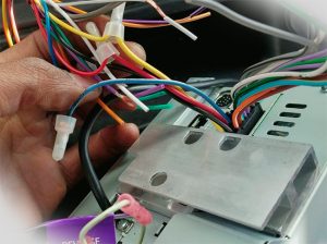
What color wires go together in a car stereo? It is mandatory to know the colors of the wires and their designation in order to work the correct connection. In all cars and stereos (Pioneer, Sony, and Kenwood, etc.) it is usual to mark the wire belonging with a certain ford stereo wiring color code. It is worth noting that stereo wires by honda radio wiring color code also differ by the presence or absence of a stripe. For example, all wires with a stripe are minus, and those without a stripe are plus.
- The battery minus is black;
- The battery plus is yellow.
Car Stereo Wiring Diagram by Wire Color on a Stereo
- Ignition plus – red;
- Left front speaker – white and white with stripe;
- Right front speaker – gray and gray with stripes;
- Left rear speaker – green and green with banding;
- Right rear speaker – purple with purple banding;
- Antenna – blue;
- Amplifier – blue with stripe; Amplifier – blue with stripe.
Car Stereo Device Options
 All car stereos are manufactured according to the standards of the company to which they belong. The aforementioned Pioneer, Kenwood, and Sony are manufactured to their companies’ standards. However, each of them has a standard ISO adapter. Likewise, each car has a standard plug for that adapter. Based on this, one of three situations can arise:
-
The first option is ideal. The car has all the wires out. Everything is connected according to the standards and under the ISO plug. There will be no difficulties in this case. You only need to connect this connector to the radio.
-
The second case is when all factory wiring harness ford radio wire harness color codes are connected correctly, but the connector does not fit. In this case, you can purchase a conductor, a lot of which are sold in specialized stores, connect the radio via a conductor and enjoy quality sound.
-
The last option: the wires are not connected to the same connector or there are no wires at all.
1DIN and 2DIN Standards
The difference between them lies in the height of the boomboxes. The number 2 in the designation of the 2DIN standard indicates that the height of the two-single receiver is 2 times greater than the device made according to the 1DIN standard. The latter boomboxes are now the most popular and widespread. Installation of dual-speaker recorders is not possible in every car, because the front panel must be provided with an appropriate landing place.
All boomboxes are divided into two types: with a branded connector, usually in the form of a plug and located on the rear wall, and with a universal connector ISO. In the first case, you should buy a branded connector for the car radio, which pinout is suitable for the desired model. If the car is equipped with an ISO socket, the other end of the branded cable should also have an ISO plug. In the second case, connect the boombox directly to the car’s ISO socket. When replacing the boombox with another one, you should look at the back and determine which socket is located there. After that, you can decide whether to purchase a proprietary plug or can connect the device to the car through the ISO socket already installed. The car radio connector pinout is done according to the ISO 10487 standard.
Bottom Line
If necessary, you can always find a color code car stereo wiring diagram or pinout table in the vehicle’s operating manual in the electrical equipment section. And this need may arise in the following cases:
- Impairment of sound reproduction quality;
- Independent replacement of original car radio by a newer or more convenient device;
- Installation and connection of additional equipment and devices (external sound amplifier, subwoofer, rearview camera, and others) to the car player.
Modern stereos are equipped with universal connectors for all types of equipment (at least it’s declared so). But in fact, some manufacturers cheat and in some cases, their connections do not match others. Thus, encouraging to buy connectors and adapters of the certain brand only. And that’s all and I hope in this article I have clearly explained how to distinguish the wires of a used stereo and what ford stereo wiring color code is. Have a nice day!


Leave a Reply